Jeanette Edlund,
Urban Bergsten  ,
Hans Arvidsson
,
Hans Arvidsson
A forest machine bogie with a bearing capacity dependent contact area: acceleration and angular orientation when passing obstacles and drawbar pull force and free rolling resistance on firm ground
Edlund J., Bergsten U., Arvidsson H. (2013). A forest machine bogie with a bearing capacity dependent contact area: acceleration and angular orientation when passing obstacles and drawbar pull force and free rolling resistance on firm ground. Silva Fennica vol. 47 no. 3 article id 1017. https://doi.org/10.14214/sf.1017
Highlights
- The Long Tracked Bogie principle (LTB) has low contact area on firm ground with low load, it increases when higher traction force is needed and on softer soil
- Free rolling resistance on firm ground was 60% of the value for a conventional bogie
- LTB appears to pass wider ditches/cavities, more smoothly with lower pitch angle, than a conventional bogie.
Abstract
The Long Tracked Bogie with contact area dependent on bearing capacity was compared to a conventional bogie. Two unloaded Vimek 608 forwarders with different bogies and with the traction from the front wheel removed were compared. Two high obstacles, 0.1 and 0.2 m high, respectively and 0.15 m in width, and two deep obstacles/ditches with a depth of 0.2 m and a width 1 and 1.5 m were used for tests. Towing tests on flat ground were done by connecting the machines to each other with a load cell in between. There were no or small differences in acceleration when passing obstacles between the two types of bogie. LTB passed wider ditches/cavities with lower pitch angles (one bogie/side passing) and 0.2 m obstacles with higher roll angles than a conventional bogie. On firm ground, free rolling resistance of the LTB was about 60% of the resistance of the conventional bogie. The drawbar pull force for the LTB was indicated to be a few percentage units higher than for the conventional bogie when it was driving with a towed machine acting as a braking force. The LTB principle might yield opportunities to improve the way we construct bogies for forest machines. Even if the contact area is low on firm ground when the machine is running with low load, it increases when higher traction force is needed and on softer soil. Further field tests are needed to evaluate the LTB when used on soft ground and with higher load as well.
Keywords
ground damages;
soft ground;
traction force
- Edlund, Sveaskog AB, SE-941 86 Piteå, Sweden E-mail jeanette.edlund@sveaskog.se
-
Bergsten,
Swedish University of Agricultural Sciences, Department of Silviculture, SE-901 83 Umeå, Sweden
E-mail
urban.bergsten@slu.se
- Arvidsson, SMP Umeå, SE-904 03 Umeå, Sweden E-mail hans.arvidsson@smp.sp.se
Received 26 March 2013 Accepted 8 October 2013 Published 10 October 2013
Views 68928
Available at https://doi.org/10.14214/sf.1017 | Download PDF

1 Introduction
Bogies of forestry vehicles are used to increase the traction and stability of the machine and to increase the ride comfort for the operator (Bygdén et al. 2004; Pijuan et al. 2012). In wet conditions and during winter, the bogie is covered with bogie tracks to create a larger contact area with the ground and thus increase the bearing capacity of the machine (Alakukku et al. 2003; Bygdén and Wästerlund 2007). The use of bogie tracks may reduce both the depth of the ruts and the soil compaction (Ansorge and Godwin 2007) and some forestry vehicles thus use bogies that allow longer tracks. Even forestry machines with caterpillar tracks have been used recently to reduce the damage to soft ground (Uusitalo et al. 2011).
However, there are some drawbacks with conventional tracked covered bogies. The rectangular contact area, creating shearing when turning (Liu et al. 2010) can easily destroy the humus and root layer of the forest, thus creating ground damage (Eliasson and Wästerlund 2007). There are machines, such as the El-forest F15, with individually steerable wheel axles that avoid shearing, but these machines are not equipped with bogie tracks (Edlund et al. 2012). Another problem is the creation of a bow wave in front of the conventional bogie that first rotates the soil particles forwards, then backwards and thus changes pore orientation and reduces pore space: thus creating soil compaction (Bygdén and Wästerlund 2007) and extra rolling resistance (Okello et al. 1994). Further, a conventional bogie has a rather heavy construction as well as being complicated and expensive to build.
To reduce existing problems with a conventional bogie, a new type of bogie has been designed, called the Long Tracked Bogie (LTB, Vimek AB). It consists of a big wheel mounted on the drive axle of the machine. On each side of the big wheel, smaller wheels are mounted, creating an angle between the ground and the bogie track (Fig. 1). This construction gives a small contact area on firm ground because only the big wheel will be in contact with the ground. On soft ground, the bogie will go deeper, creating a bigger contact area (higher bearing capacity) with the ground. The softer the ground is, the more the contact area with the bogie will increase (up to the full width of the smaller wheels and the tracks).
The objectives of this study were to validate results of a simulation study (Edlund et al. 2013) and compare the LTB and a conventional bogie with respect to their ability to pass obstacles and the smoothness with which these obstacles are passed. Since the contact area of the LTB bogie is small when standing idle on firm ground, another objective was to quantify free rolling resistance and the drawbar pull force on firm ground.
2 Material and methods
Two unloaded forwarders (Vimek 608) with different types of bogies fitted on the rear axle were tested (same size of front wheels 405/70-24); the machines were reversed when driven over the obstacles so that the bogies tested would pass the obstacles first.
One machine had a conventional bogie with a special cog drive system (Robson drive) installed between the two bogie wheels (tyre size 400/15.5, Olofsfors Eco Track 1.2 m long) and the other was fitted with the LTB (405/70-24 and two Ø50cm wheels, custom-made tracks 2.0 m long with cross members 9.5x45.5 cm and 10.5 cm distance between the cross members; Fig. 1). The LTB was a prototype version e.g. tracks and wheels were not completely matched. Cavities were cut with a knife in the wheel to increase the contact/friction between wheel and tracks.
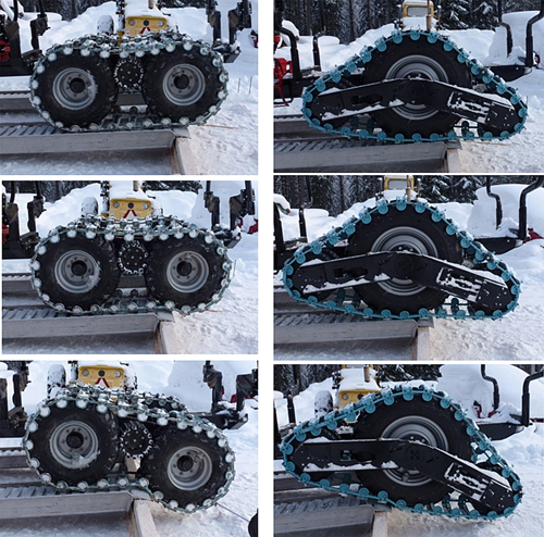
Fig. 1. Pictures of the two bogies when driving over an edge (e.g. cavity, ditch). The conventional bogie is shown on the left and the LTB on the right.
The minimum contact area was calculated by measuring the total area underneath all wheels and bogies that made contact with the ground whilst standing on firm ground (Conv. 0.57 m2; LTB 0.28 m2). The maximum contact area was calculated in the same manner, but here we assumed that the wheels and bogies had sunk so that the contact area was maximized (Conv. 0.91 m2, LTB 1.22 m2). The contact areas from the track cross members were also determined by calculating the area from one cross member and multiplying it with the number of cross members touching the ground. For Conv. the contact area was 0.24 m2 with 8 cross members always touching the ground while for LTB the minimum and maximum number of cross members touching the ground was 2 (0.08 m2) and 14 (0.60 m2), respectively.
The weight of the machines was measured with two vehicle scales, one under each wheel/bogie (total weight Conv. 4.95 ton, LTB 5.71 ton). The other wheels that were not measured were lifted from the ground with wooden planks to level the machine. Due to this, the total weight of the machines cannot be exactly determined, and thus differs from the producer specifications. According to the producer, one single LTB bogie was 155 kg heavier, mainly due to longer tracks, than a conventional bogie.
To test the ability to pass obstacles smoothly, an accelerometer was attached to the frame between the bogies (centred between bogies at the same height on both machines). The accelerometer (Xsens MTi-G) recorded the momentary acceleration (m/s–2) in three directions/axes as well as the orientation around these axes (roll: x-axis and pitch: y-axis). Angular resolution was 0.05 deg, accuracy: roll/pitch <0.5 deg. The acceleration vector was calculated by taking the square root of the sum of the squared acceleration in each direction (Edlund et al. 2013). The maximum acceleration vector (peak acceleration) was calculated for each passage. The sum of the acceleration vectors was calculated for three seconds (300 measurements) with the peak acceleration in the middle of the time period (total acceleration).
Obstacles with different heights and depths were built from wood and attached to the ground using nails, snow and ice. The two high obstacles were 0.1 and 0.2 m high, respectively and 0.15 m in width. Each obstacle/rectangular box was about 4 metres in length allowing the two machines to drive over with both bogies perpendicular when necessary. Each high obstacle was passed by the machines with both bogies driving over the obstacle simultaneously and with only one bogie driving over the obstacle (five replications for each machine/bogie and obstacle height).
The deep obstacles were constructed as ditches with a depth of 0.2 m and a width of 1, 1.5 and 1.9 m. The ditches were driven over by only one bogie of each machine (five replications). However, the conventional bogie, contrarily to the LTB, was not able to handle the 1.9 m ditch, thus only widths up to 1.5 m were compared.
For all tests, the machines were driven unloaded at a constant speed of approximately 2.4 km/h. The speed was held constant by driving at a certain gear at full throttle and the actual speed was determined by driving a fixed distance and measuring the time. The same speed was used when performing tests of below. Since the cabin/front part of the machines were not fitted with bogies, it was not comfortable for the driver to drive at a higher speed.
Towing tests were carried out in summer on a firm forest road. These were done by connecting the machines to each other with straps, with a load cell in between. The traction from the front wheel was removed from both machines by decoupling the planet gears from the planetary gearbox. Thus, all the traction came from the bogies. We measured the free rolling resistance in neutral gear as well as the drawbar pull force (three replications). For the drawbar pull tests, the test machine was driven at constant speed for approximately 75 metres while the other machine was pulled behind with increasing braking force until 100% slip was reached. The load cell measured the force from the pulling machine acting on the machine being pulled. Slip was measured by simultaneously measuring the distance the machine travelled as well as the revolutions of the drive axle. Both measurements were made by using encoders sending pulses for each revolution. One encoder was placed on the axis of the drive axle with another placed on an extra wheel attached to the machine and rolling beside it when driving.
Data were tested for normality and equal variance prior to analysis (Levene’s test). Analysis of variance was used to investigate the effects of the bogies on acceleration and angular orientation, as well as on free rolling resistance and drawbar pull force (incl. polynomial fitting of data as well). Treatment effects were considered significant if p ≤ 0.05.
3 Results
3.1 Acceleration and angular orientation when passing obstacles
The only statistical difference that could be established between the bogies for the 0.1 m high obstacle was the total acceleration when passing the obstacle with one side/bogie (Table 1). The conventional bogie had a 0.4% higher total acceleration. No statistical differences for acceleration could be established for the 0.2 m obstacle. Analysing the data for the 0.1 m and 0.2 m obstacle together established a statistical difference for the total acceleration between the two types of bogie (0.4% lower for the LTB).
| Table 1. Results of total acceleration (ms–2), peak acceleration, roll and pitch (°) for LTB and a conventional bogie. The treatments are considered statistically different when the p-value is ≤ 0.05. Here pp means bogies passing parallel and op means one bogie passing the obstacle. | ||||||||||||
| Obstacle | Total acceleration | Peak acceleration | Roll | Pitch | ||||||||
| Conv. | LTB | p-value | Conv. | LTB | p-value | Conv. | LTB | p-value | Conv. | LTB | p-value | |
| 0.1m pp | 995.9 | 986.6 | 0.160 | 19.8 | 19.3 | 0.710 | 5.1 | 4.4 | 0.497 | 3.9 | 3.5 | 0.724 |
| 0.1m op | 994.1 | 989.8 | 0.013 | 15.5 | 16.0 | 0.723 | 4.5 | 8.2 | 0.082 | 3.3 | 2.9 | 0.145 |
| 0.2m pp | 996.4 | 990.4 | 0.358 | 22.3 | 20.8 | 0.372 | 7.5 | 4.4 | 0.044 | 5.0 | 3.3 | 0.010 |
| 0.2m op | 996.2 | 992.8 | 0.271 | 19.3 | 18.1 | 0.218 | 4.7 | 13.1 | <0.001 | 4.0 | 3.3 | 0.153 |
| 1m ditch | 994.4 | 990.9 | 0.145 | 14.3 | 14.9 | 0.635 | 5.8 | 6.5 | 0.546 | 5.6 | 2.7 | 0.002 |
| 1.5m ditch | 993.2 | 992.7 | 0.859 | 14.5 | 16.0 | 0.480 | 7.5 | 9.3 | 0.146 | 5.1 | 3.4 | 0.006 |
The LTB had a few degrees lower maximum values for roll and pitch when passing the 0.2 m obstacle with both sides simultaneously (Table 1). On the other hand, when passing the 0.2 m obstacle with one side of the machine, the maximum roll value was lower for the conventional bogie, 4.7 compared to 13.1 degrees. There was also a significant difference in pitch, with lower values for LTB, when passing the 1 m and 1.5 m ditches with one bogie.
3.2 Rolling resistance and drawbar pull force
The free rolling resistance of the LTB was about 60% of the resistance of the conventional bogie (close to significance) (Table 2). The differences in distance measured by encoders on the drive axle and the extra wheel were below 1% for both bogies during the rolling resistance test (not presented), i.e., there was almost no skid/slip during the test.
| Table 2. Free rolling resistance (N) for the LTB and a conventional bogie. | |||
| Parameter | Conv. bogie | LTB | p-value |
| Mean | 4230.5 | 2551.2 | 0.055 |
| Max | 7938.5 | 6058.9 | 0.942 |
The drawbar pull force test showed large variation for both bogies. Thus, all pull force data from all replications (794 pairs of force and slip values in total) were pooled and fitted to polynomial functions with YConv = 9016 + 1131slip – 459slip2 (R-square 0.39) and YLTB = 9222 + 1829slip – 1103slip2 (R-square 0.57). According to the fitted functions, the LTB showed about 3 and 4% higher pull force at 75 and 90% slip, respectively, than the conventional bogie. As calculated on the 10% highest values of drawbar pull force, the LTB showed about 5% higher maximum pull force (100 105 compared to 95 470 N). The front wheel of the reversing LTB was pushed down to the ground when the drawbar pull force increased (Fig. 2), increasing the contact area. When the pull force reached its maximum for the conventional bogie, the rear wheel of the reversing bogie was lifted, thus decreasing the contact area.
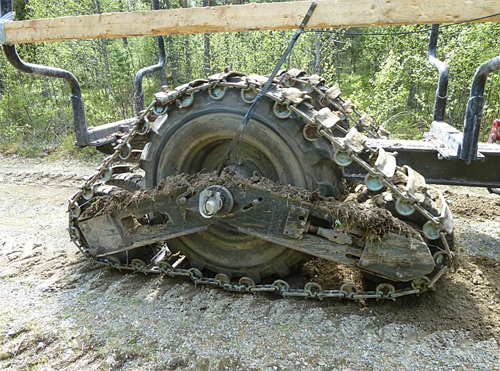
Fig. 2. The rear small wheel of the reversing LTB was pushed down to the ground when the drawbar pull force reached its maximum, thus creating a higher contact area.
4 Discussion
According to our results and the simulation study by Edlund et al. (2013), the LTB bogie exhibits some properties that could be superior to a conventional bogie. It seems that the LTB bogie will somewhat decrease the acceleration for the driver (pronounced in the simulation study probably due to higher speed of vehicles), creating a more comfortable ride in the forest machine. It appears also to be able to pass wider ditches/cavities, and to do it more smoothly with lower pitch angle than a conventional bogie. However, the roll angle was not lower when passing obstacles/cavities. The rolling resistance on firm ground at low load is also lower for the LTB which can reduce fuel consumption. At the same time it seems that drawbar pull force could be increased on firm ground when needed, thanks to the construction principle of the LTB, but further test are required to evaluate this.
One of the possible reasons why the free rolling resistance pulling the LTB on firm ground was lower, could be related to the forces required to move a conventional bogie (Pijuan et al. 2012). The rolling resistance can vary between different bogies as well as between different bogie tracks due to e.g. contact area and friction. In this study the track types of the two machines/bogies were similar but they differed in length (0.8 m longer tracks of the LTB) and in weight (155 kg heavier bogie of the LTB due to longer tracks and because there was three wheels instead of two). Since the weight difference was relatively small compared to machine weight (ca 5 ton), the differences between the bogies in drawbar pull force and free rolling resistance, should mainly be related to construction principles.
The contact area on soft ground should, in general, be higher for the LTB compared to a conventional bogie and the drawbar pull force might be greater if the bow wave is minimised; this could increase the accessibility in the forest both in snow and on soft ground. With further development of the LTB the angle between the small wheels and the ground (Figs. 1 and 2) could be adjustable by having a flexible instead of a fixed bonding between the wheels. The small wheels can be actively lifted when driving on firm ground and lowered when driving in soft ground.
Further tests where the bogies are tested under load in different forest environments, including soft ground, should focus on the shearing effects of the bogies and rut formation as well (cf. Edlund et al. 2013).
References
Alakukku L., Weisskopf P., Chamen W., Tijink F., van der Linden J., Pires S., Sommer C., Spoor G. (2003). Prevention strategies for field traffic-induced subsoil compaction: a review: Part 1. Machine/soil interactions. Soil and Tillage Research 73: 145–160. http://dx.doi.org/10.1016/S0167-1987(03)00107-7.
Ansorge D., Godwin R.J. (2007). The effect of tyres and a rubber track at high axle loads on soil compaction, Part 1: Single axle-studies. Biosystems Engineering 98: 115–126. http://dx.doi.org/10.1016/j.biosystemseng.2007.06.005.
Bygdén G., Wästerlund I. (2007). Rutting and soil disturbance minimized by planning and using bogie tracks. Forestry Studies 46: 5–12.
Bygdén G., Eliasson L., Wästerlund I. (2004). Rut depth, soil compaction and rolling resistance when using bogie tracks. Journal of Terramechanics 40: 179–190. http://dx.doi.org/10.1016/j.jterra.2003.12.001.
Edlund J., Löfgren B., Bergsten U. (2012). Effects of two different forwarder steering and transmission drive systems on rut dimensions. Journal of Terramechanics 49: 291–297. http://dx.doi.org/10.1016/j.jterra.2012.03.004.
Edlund J., Keramati E., Servin M. (2013). A long-tracked bogie design for forestry machines on soft and rough terrain. Journal of Terramechanics. [Accepted]. http://dx.doi.org/10.1016/j.jterra.2013.02.001.
Eliasson L., Wästerlund I. (2007). Effects of slash reinforcement of strip roads on rutting and soil compaction on a moist fine-grained soil. Forest Ecology and Management 252: 118–123. http://dx.doi.org/10.1016/j.foreco.2007.06.037.
Liu K., Ayers P., Howard H., Anderson A. (2010). Influence of soil and vehicle parameters on soil rut formation. Journal of Terramechanics 47: 143–150. http://dx.doi.org/10.1016/j.jterra.2009.09.001.
Okello J., Dwyer M., Cottrell F. (1994). The tractive performance of rubber tracks and a tractor driving wheel tyre as influenced by design parameters. Journal of Agricultural Engineering Research 59: 33–43. http://dx.doi.org/10.1006/jaer.1994.1062.
Pijuan J., Comellas M., Nogués M., Roca J., Potau X. (2012). Active bogies and chassis levelling for a vehicle operating in rough terrain. Journal of Terramechanics 49: 161–171. http://dx.doi.org/10.1016/j.jterra.2012.03.001.
Uusitalo J., Ala-Ilomäki J., Salomäki M., Niemistö P. (2011). New solutions in management and harvesting of peatland forests. Presentation at Oscar Seminar Soil and Machine Workshop, Hyytiälä, Finland.
Total of 11 references
Send to email
